Spanning Tree Protocol(STP) is used to prevent loops in the switch networks.Its defined in IEEE 802.1D standard. In order to understand how STP avoids loops, first we should know how loops are formed in the switched network. The switch floods the unknown unicast frames through all the other ports except the port on which it is received. If there are redundant links to the same destination and all the switches floods the unknown unicast frames then loops are formed.

Lets say PC-1 wants to send a frame to PC-3.And lets assume that all the swithes in the above network does not have the MAC address of PC-3 in their MAC address table and PC-3 is shutdown.In this case when PC-1 sends a frame with the destination MAC address of PC-3 then switch-1 receives the frame and floods it out of the other ports. Similarly Switch2 receives the frame and floods it out of the other ports.The same is the case with switch-3 and switch-4. Now Switch1 receives the same frame which it sent as a broadcast from switch 4. And the above process of flooding the frame repeats till the network is congested.This is called looping of frames.
Once STP is enabled on all the switches in the network,the switches starts sending messages.These messages are called BPDU's(Bridge Protocol Data Unit). The BPDU's will have the source MAC address of the port through which they came out and destination address would be the STP multicast address 01-80-C2-00-00-00.
1)Configuration BPDU:-
2)Topology change notification(TCN) BPDU:
In the STP enabled switched network, every switch has a different bridge ID. This bridge ID identifies that switch among all the other switches.
The bridge ID consists of two parts.
1)Bridge Priority
2)MAC Address
The length of the bridge ID is 8 bytes where the bridge priority is 2 bytes and MAC address is 6 bytes.
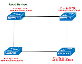
In the initial stages of the root bridge election process, each switch assumes itself as the root bridge and starts sending out the BPDU's with the root bridge ID as its own bridge bridge ID and the sender bridge ID also as its own Bridge ID. When the switch receives the BPDU's from other switches, it compares the root bridge ID of the received BPDU to the root Bridge ID in its own BPDU. If the root bridge ID in the received BPDU is lower value then that value is replaced as the root bridge ID in its BPDU and starts sending the new root Brige ID in its BPDU messages.This process continues till all the switches agree on the lowest bridge ID as the Root Bridge ID.If the bridge priority is having the same value then the bridge ID with lowest MAC address will be chosen as the root bridge ID.


For the segment Switch1-Switch2, the port F0/1 of Switch1 has the cost of "0" to the root bridge where as the port F0/1 of switch2 has the cost of 19 to the root bridge.Since Switch1's F0/1 port has the lower cost on that segment it is chosen as the Designated port.
For the segment Switch1-Switch4, the port F0/2 of Switch1 has the cost of "0" to the root bridge where as the port F0/1 of switch4 has the cost of 19 to the root bridge.Since Switch1's F0/2 port has the lower cost on that segment it is chosen as the Designated port.
For the segment Switch2-Switch3, the port F0/2 of Switch2 has the cost of "19" to the root bridge where as the port F0/1 of switch3 has the cost of 38 to the root bridge and also it is a Root port.Since Switch2's F0/1 port has the lower cost on that segment it is chosen as the Designated port.
For the segment Switch4-Switch3, the port F0/2 of Switch4 has the cost of "19" to the root bridge where as the port F0/2 of switch3 has the cost of 38 to the root bridge.Since Switch4's F0/2 port has the lower cost on that segment it is chosen as the Designated port.

Lets say PC-1 wants to send a frame to PC-3.And lets assume that all the swithes in the above network does not have the MAC address of PC-3 in their MAC address table and PC-3 is shutdown.In this case when PC-1 sends a frame with the destination MAC address of PC-3 then switch-1 receives the frame and floods it out of the other ports. Similarly Switch2 receives the frame and floods it out of the other ports.The same is the case with switch-3 and switch-4. Now Switch1 receives the same frame which it sent as a broadcast from switch 4. And the above process of flooding the frame repeats till the network is congested.This is called looping of frames.
Effect of STP
STP stops the loops from formning by shutting down the redundant links.STP operation
Once STP is enabled on all the switches in the network,the switches starts sending messages.These messages are called BPDU's(Bridge Protocol Data Unit). The BPDU's will have the source MAC address of the port through which they came out and destination address would be the STP multicast address 01-80-C2-00-00-00.
There are two types of BPDU.
1)Configuration BPDU:-
2)Topology change notification(TCN) BPDU:
Root Bridge
Once STP is enabled on the swithed network , all the switches in the network will selection switch as the reference switch.This switch is called as the root bridge.In the STP enabled switched network, every switch has a different bridge ID. This bridge ID identifies that switch among all the other switches.
The bridge ID consists of two parts.
1)Bridge Priority
2)MAC Address
The length of the bridge ID is 8 bytes where the bridge priority is 2 bytes and MAC address is 6 bytes.
Bridge Priority
Bridge priority tells about the importance of the switch compared to other switches in that network.Its value can range from 0 to 65,535 and its default value is 32,768.,MAC Address
This is the MAC address of the switch.Root Bridge Election
In the initial stages of the root bridge election process, each switch assumes itself as the root bridge and starts sending out the BPDU's with the root bridge ID as its own bridge bridge ID and the sender bridge ID also as its own Bridge ID. When the switch receives the BPDU's from other switches, it compares the root bridge ID of the received BPDU to the root Bridge ID in its own BPDU. If the root bridge ID in the received BPDU is lower value then that value is replaced as the root bridge ID in its BPDU and starts sending the new root Brige ID in its BPDU messages.This process continues till all the switches agree on the lowest bridge ID as the Root Bridge ID.If the bridge priority is having the same value then the bridge ID with lowest MAC address will be chosen as the root bridge ID.

Root Port
Once the Root Bridge is elected, the non root switches will select a port which leads to the root bridge as the Root Port. The port with the minimum path cost to the root bridge is elected as the Root Port.Only the nonroot switches will have the root port. The Root Bridge will not have any root port.
Designated Port
A Designated Port is the port on a "Local Area Network (LAN) segment" with the minimum cost to the root bridge.
For the segment Switch1-Switch2, the port F0/1 of Switch1 has the cost of "0" to the root bridge where as the port F0/1 of switch2 has the cost of 19 to the root bridge.Since Switch1's F0/1 port has the lower cost on that segment it is chosen as the Designated port.
For the segment Switch1-Switch4, the port F0/2 of Switch1 has the cost of "0" to the root bridge where as the port F0/1 of switch4 has the cost of 19 to the root bridge.Since Switch1's F0/2 port has the lower cost on that segment it is chosen as the Designated port.
For the segment Switch2-Switch3, the port F0/2 of Switch2 has the cost of "19" to the root bridge where as the port F0/1 of switch3 has the cost of 38 to the root bridge and also it is a Root port.Since Switch2's F0/1 port has the lower cost on that segment it is chosen as the Designated port.
For the segment Switch4-Switch3, the port F0/2 of Switch4 has the cost of "19" to the root bridge where as the port F0/2 of switch3 has the cost of 38 to the root bridge.Since Switch4's F0/2 port has the lower cost on that segment it is chosen as the Designated port.